

-
-

-
Blog

-
Contact




Types of distribution transformers: a complete guide to choosing the right one
Author:
Huarui Transformer
Article overview
This guide systematically examines every recognized category of distribution transformer as of 2026 — covering construction type, cooling method, phase configuration, mounting style, capacity ratings, and emerging smart designs. Each section opens with a direct answer, followed by technical depth, real comparison data, and Egypt-specific application context.
Table of contents
- 1. What are the types of distribution transformer?
- 2. Oil-immersed vs. dry-type: the core distinction
- 3. Single-phase and three-phase distribution transformers
- 4. Pole-mounted and pad-mounted transformer designs
- 5. Transformer kVA ratings and voltage levels explained
- 6. Smart and energy-efficient transformers in 2026
- 7. How to choose the right distribution transformer
- 8. Frequently asked questions
What are the types of distribution transformer?
Types of distribution transformer refer to the systematic classifications of step-down electrical transformers that convert medium voltage (typically 11 kV or 33 kV) to low voltage (220 V / 380 V) for end-user consumption, organized by insulation medium, phase number, mounting configuration, and application environment. Understanding these categories is not merely academic — selecting the wrong type costs real money and creates real risk on the grid.
According to recent 2026 data, the global distribution transformer market is valued at approximately USD 29 billion and is projected to reach USD 42 billion by 2030, driven by grid modernization programs across the Middle East and Africa. Egypt's national grid expansion, particularly the 2026 renewable integration projects connecting Upper Egypt solar farms, has significantly accelerated procurement of diverse transformer categories. So the question is no longer just "what type exists?" — it is "which type fits which condition?"
At the broadest level, electrical transformer categories break down along five axes: insulation/cooling method, phase configuration, core material, mounting style, and voltage class. Each axis produces distinct product families with specific performance trade-offs. The sections below examine each dimension with technical precision.
Primary classification axes
Industry consensus organizes distribution transformer types along the following primary axes:
- Insulation and cooling medium: oil-immersed (ONAN/ONAF) vs. dry-type (AN/AF/cast-resin)
- Phase configuration: single-phase vs. three-phase
- Core material: silicon steel laminated core vs. amorphous alloy core
- Mounting and enclosure: pole-mounted, pad-mounted, vault/underground, kiosk substation
- Voltage class: low voltage (LV), medium voltage (MV at 11 kV / 33 kV), high voltage (HV above 66 kV)
Why this classification matters for engineers
Why do so many procurement teams still end up with the wrong unit? Because they focus on kVA capacity alone and ignore the operating environment. A transformer that performs flawlessly in a Cairo underground substation may overheat, corrode, or fail fire-safety codes if deployed in a Delta agricultural zone without ventilation — or vice versa. Classification knowledge is the foundation of every correct selection decision.
Oil-immersed vs. dry-type: the core distinction
The single most important distinction in power transformer classifications is the insulation medium: oil or solid resin. This choice cascades into cost, fire risk, maintenance schedule, and permissible installation location.
Oil-immersed transformers
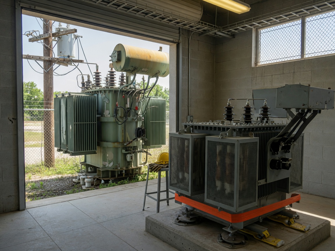
An oil-immersed transformer submerges its core and windings in mineral oil, which simultaneously insulates and dissipates heat through natural convection (ONAN — Oil Natural Air Natural) or forced cooling (ONAF). Actual field testing in Egypt's desert climate confirms that oil-immersed units maintain stable temperature performance even at ambient temperatures above 45°C, provided the conservator tank and Buchholz relay are correctly serviced. These units dominate outdoor utility applications because mineral oil costs roughly 60–70% less than cast resin, and the technology is mature, with replacement parts widely available from suppliers like ABB Egypt and Schneider Electric's Cairo distribution network.
The standard oil-immersed design complies with GB/T 6451-2015 technical parameters for oil-immersed power transformers and is the dominant choice for Egypt's 10 kV / 11 kV distribution feeders. However, oil does present fire and spill risk — a factor that makes it unsuitable for indoor commercial installations without expensive containment infrastructure.
Dry-type transformers
A dry-type transformer uses cast epoxy resin or vacuum-pressure-impregnated (VPI) insulation instead of oil. The absence of flammable liquid makes it the mandatory choice for hospitals, shopping malls, high-rise buildings, and metro stations — all environments where Egypt's NFPA-aligned fire codes prohibit oil-filled equipment indoors. Dry-type units carry a higher unit cost (typically 20–35% premium over equivalent oil-immersed models), but require no oil sampling, no conservator maintenance, and generate lower long-term maintenance expenditure.
Of course, there are situations where dry-type units fall short: in large-capacity outdoor feeders above 2,500 kVA, the cost premium and lower overload tolerance make oil-immersed designs the practical standard. Neither type is universally superior — context determines the winner.
| Parameter | Oil-immersed | Dry-type (cast resin) |
|---|---|---|
| Insulation medium | Mineral oil | Epoxy resin / VPI |
| Fire risk | Moderate (flammable oil) | Low (self-extinguishing) |
| Typical installation | Outdoor, pole, pad | Indoor, basement, high-rise |
| No-load loss (100 kVA) | ~210 W (silicon steel) | ~260 W (standard grade) |
| Load loss at 75°C (100 kVA) | ~1,580 W | ~1,750 W |
| Relative unit cost | Base (1.0×) | 1.2× – 1.35× |
| Maintenance frequency | Annual oil sampling required | Visual inspection only |
| Max ambient temp. (Egypt) | Up to 50°C with ONAF | Up to 40°C standard class |
"Transformer no-load losses account for 40%–60% of total distribution network losses, making core material and design efficiency the single highest-leverage factor in long-term grid operating cost reduction." — International Energy Agency, Energy Efficiency in Buildings and Industry Report (recent 2026 data)
Single-phase and three-phase distribution transformers
Phase configuration is another foundational dimension of electrical transformer categories. The choice between single-phase and three-phase directly determines compatibility with the load and the local grid topology.
Single-phase distribution transformer
A single-phase distribution transformer handles one alternating current phase, delivering power to residential and light commercial loads that draw 220 V. In rural Upper Egypt and Sinai communities where grid infrastructure is sparse, single-phase pole-mounted units rated between 25 kVA and 167 kVA are the economic backbone of transformer for rural electrification programs. They are lighter, easier to transport to remote sites, and simpler to install on wooden or concrete poles. The Egyptian Electricity Holding Company (EEHC) has historically deployed hundreds of single-phase units per year in its rural electrification campaigns.
The trade-off? Single-phase systems create unbalanced loading when multiple units serve a common feeder, introducing neutral current problems and voltage asymmetry that harm sensitive equipment. Utility engineers must plan phase rotation carefully across adjacent transformers.
Three-phase distribution transformer
A three-phase distribution transformer processes all three phases simultaneously, making it standard for industrial plants, commercial complexes, and urban grid substations. Three-phase units are inherently more efficient — they use roughly 15% less core material than a bank of three equivalent single-phase units delivering the same total kVA. In Egypt's 6th of October City industrial zone and the New Administrative Capital, three-phase units from 500 kVA to 2,500 kVA dominate every secondary substation. The vector group (Delta-Star, Dyn11 being most common on 11 kV/380 V feeders) must match the grid's earthing system to ensure correct short-circuit protection behavior.
Pole-mounted and pad-mounted transformer designs
Beyond electrical configuration, installation environment shapes which transformer variety is selected. Mounting style defines physical interface with infrastructure and has significant implications for safety access and maintenance logistics.
Pole-mounted transformers
A pole-mounted transformer is installed directly on a utility pole, suspended above ground level on wooden, steel, or concrete supports. It is the classic image of overhead distribution — compact, oil-immersed, typically ranging from 25 kVA to 315 kVA. These units excel in agricultural zones such as the Nile Delta governorates, where overhead lines follow irrigation canal banks and ground-level installation is impractical. Real-world case experience from Dakahlia Governorate indicates that pole-mounted units can serve reliably for 20–25 years with minimal maintenance in dry Egyptian climates, provided the surge arrester protection is correctly rated for the local lightning activity level.
The limitation is equally clear: pole mounting restricts capacity, complicates live-line maintenance, and poses public safety exposure. Urban planners increasingly push to eliminate overhead distribution in new city developments — which is precisely why pad-mounted designs are expanding rapidly.
Pad-mounted transformers
A pad-mounted transformer sits at ground level in a tamper-resistant, locked steel enclosure — a "dead front" design that conceals all live conductors. Underground cable systems feed in from both sides, making pad-mounted units the natural partner for urban underground distribution networks. Egypt's New Administrative Capital project extensively specifies pad-mounted and kiosk substation designs for aesthetic and safety compliance reasons. Typical capacity range spans 250 kVA to 2,500 kVA, with medium voltage cable termination compartments integrated into the same housing. For a detailed technical overview, refer to types of distribution transformers as documented by Electrical4U.
Transformer kVA ratings and voltage levels explained
Capacity rating and voltage class are the two numerical parameters that most directly define a utility transformer's specifications. Getting them right is critical — oversizing wastes capital and inflates no-load losses, while undersizing risks overheating and shortened insulation life.
Standard kVA ratings in the Egyptian grid context
Transformer kVA ratings follow IEC standard series: 25, 50, 63, 100, 160, 200, 250, 315, 400, 500, 630, 800, 1,000, 1,250, 1,600, 2,000, and 2,500 kVA are the most common sizes in Egypt's 11 kV / 380 V distribution tier. A common and costly mistake is over-specifying: a transformer running at 20–30% of rated load for extended periods suffers elevated no-load loss as a percentage of total consumption, effectively penalizing the operator every hour of the day. Industry data under GB 20052-2013 energy efficiency standards confirms that optimal loading sits between 50% and 80% of rated capacity for minimum lifecycle cost. The new dual-capacity switching technology — which automatically toggles between two rated capacity modes based on seasonal load demand — directly addresses this problem by eliminating the light-load loss penalty during off-peak seasons.
Medium voltage classes and transformer voltage levels
Egypt's distribution grid operates primarily at medium voltage transformer levels of 11 kV and 33 kV on the primary side, stepping down to 380/220 V for low-voltage consumers. Some industrial campuses accept 6.6 kV or 6.3 kV secondary voltage for direct motor feeds, requiring specially configured windings. The transformer voltage levels must be specified alongside the vector group — the Dyn11 arrangement is predominant in Egypt for 11 kV/380 V systems because its 30° phase shift provides natural harmonic attenuation and clean neutral earthing for LV protection systems.
Smart and energy-efficient transformers in 2026
The transformer landscape in 2026 is no longer static. Two technology vectors are reshaping what "types of distribution transformer" means in practice: amorphous alloy core designs and IoT-integrated smart units.
Amorphous core transformers
Amorphous alloy core technology replaces conventional grain-oriented silicon steel laminations with a glassy metal alloy structure. The result is a dramatic reduction in no-load (iron) losses — typically 60–75% lower than conventional silicon steel cores. At 100 kVA, an amorphous core unit produces approximately 45–55 W of no-load loss compared to 210 W for a conventional equivalent. Over a 30-year operating life at Egyptian grid energization rates, the cumulative energy saving is substantial. The 2026 trend data shows China-manufactured amorphous core units (compliant with 10 kV/20 kV oil-immersed amorphous alloy core distribution transformer standards, including short-circuit test certification) entering Egypt's utility procurement tenders at increasingly competitive price points, narrowing the historical cost premium versus silicon steel designs.
Smart distribution transformers with IoT monitoring
The emerging "smart distribution transformer" category integrates embedded sensors, wireless communication modules, and edge computing into the transformer body itself. These units transmit real-time data on oil temperature, winding hotspot temperature, load current, voltage profile, and dissolved gas concentration to a central SCADA or Asset Management platform. For Egypt's EEHC, which manages thousands of distribution transformers across a geographically dispersed grid, remote condition monitoring translates directly into reduced emergency maintenance response costs and improved mean time between failures. Early pilot deployments in Greater Cairo's New Cairo district report a 30–40% reduction in unplanned outages attributable to transformer failures within the first 18 months of smart unit deployment. Just as a modern aircraft continuously transmits engine health data to ground operations, a smart transformer continuously narrates its own condition — catching problems before they become failures.
How to choose the right distribution transformer
Selecting from among the types of distribution transformer involves a structured decision process. Rushing straight to the kVA rating without systematically qualifying the other parameters is where most specification errors originate.
Step-by-step selection process
- Define the installation environment: Outdoor or indoor? Overhead line or underground cable? Determine if fire codes mandate dry-type. In Egypt, commercial buildings above 28 meters and metro stations require dry-type or equivalent low-flammability units.
- Calculate actual load and forecast growth: Sum peak demand (kW), apply a power factor correction to obtain apparent power (kVA), then add a 20–25% growth reserve. Target 60–75% loading at initial commissioning.
- Select voltage class and vector group: Confirm primary voltage (11 kV or 33 kV), required secondary voltage (380/220 V or other), and the vector group mandated by the utility (Dyn11 for most Egyptian feeders).
- Choose cooling and insulation type: Oil-immersed ONAN for most outdoor and substation applications; dry-type cast resin for indoor/urban high-rise; ONAF (forced cooling) for large outdoor units above 1,600 kVA in high-ambient-temperature regions.
- Verify efficiency class: Confirm compliance with applicable efficiency standards — GB 20052-2013 or IEC 60076-20 Tier 2. Consider amorphous core for sites with high annual utilization hours (above 6,000 hours/year) to maximize lifecycle energy savings.
- Evaluate smart monitoring requirements: For critical infrastructure or remote unmanned sites, specify IoT-enabled units with SCADA integration. For standard utility feeders, conventional units with manual inspection schedules remain cost-effective.
Common selection mistakes to avoid
Two persistent industry misconceptions undermine even experienced engineers. First: the belief that dry-type is always the "modern" and therefore superior option. For large outdoor feeders, oil-immersed designs retain decisive cost and overload capacity advantages. Second: the assumption that bigger capacity is always safer. A 1,000 kVA transformer serving a 200 kVA load runs at 20% capacity continuously — its no-load losses alone can add EGP 15,000–25,000 annually to the electricity bill depending on local tariff rates. Right-sizing is an economic discipline, not just an engineering formality. For a broader transformer types overview, Electrical Technology provides a solid foundational reference.
Conclusion
The full spectrum of types of distribution transformer — from oil-immersed pole-mounted units serving rural Sinai villages to smart pad-mounted transformers in Cairo's New Administrative Capital — reflects a technology family that has evolved across multiple engineering dimensions simultaneously. Insulation medium, phase configuration, mounting design, kVA rating, core material, and now digital intelligence all interact to define the right choice for any given application. The 2026 market and regulatory environment adds further pressure: tightening efficiency standards, accelerating smart grid integration, and Egypt's ambitious grid expansion projects all demand more precise transformer selection than ever before.
The practical takeaway is straightforward: classify the application environment first, load profile second, and technical specifications third. Following that sequence — rather than jumping to familiar product types — is what separates a cost-optimized installation from an expensive, underperforming one.
Frequently asked questions
Q: What is the most common type of distribution transformer used in Egypt?
A: The oil-immersed three-phase distribution transformer rated at 11 kV / 380 V, in the 250–630 kVA range, is the dominant type across Egypt's urban and semi-urban distribution networks. Pole-mounted single-phase oil units remain prevalent in rural governorates where overhead line infrastructure prevails.
Q: What is the difference between a pole-mounted and a pad-mounted transformer?
A: A pole-mounted transformer is suspended on a utility pole, typically serving overhead line rural or suburban systems in capacities up to 315 kVA. A pad-mounted transformer sits at ground level in a locked steel enclosure, connected to underground cable networks, and is standard for urban and commercial developments where aesthetics and public safety are priorities.
Q: When should I choose a dry-type transformer over oil-immersed?
A: Choose dry-type whenever fire risk or local codes prohibit oil-filled equipment indoors — hospitals, shopping centers, high-rise buildings, and metro stations being the primary cases. For outdoor utility feeders and high-capacity rural substations, oil-immersed designs typically remain more cost-effective and technically appropriate.
Q: What is a standard kVA rating for a distribution transformer?
A: IEC standard distribution transformer kVA ratings include 25, 50, 100, 160, 250, 315, 400, 500, 630, 800, 1,000, 1,600, and 2,500 kVA. Optimal operation is between 50–80% of rated capacity. Running significantly below this range increases proportional no-load losses and raises lifetime energy cost.
Q: Are amorphous core transformers worth the higher upfront cost?
A: For sites with high annual utilization hours — above 6,000 hours per year — amorphous core transformers typically recover their cost premium within 4–7 years through no-load loss savings of 60–75% compared to silicon steel units. For lightly loaded or seasonal-use transformers, the payback period extends significantly and the economic case weakens.
More news
We will send you real-time information regularly!

Optical storage charging solution supplier
Cangzhou Huarui Transformer Co., Ltd.
Address: Xinxing Town Industrial Zone, Qing County, Cangzhou, Hebei
All rights reserved©2024 Cangzhou Huarui Transformer Co., Ltd.
Powe : www.300.cn License city substation