

-
-

-
Blog

-
Contact




Power transformer protection: a complete guide to methods, relays, and fault prevention
Author:
Huarui Transformer
Article overview
This guide covers the complete spectrum of power transformer protection — methods, relay types, fault detection, IEC compliance, and 2026 smart monitoring trends. Targeted at protection engineers and technical decision-makers across Saudi Arabia and the GCC.
Table of contents
- 1. What is power transformer protection?
- 2. Core protection methods and how they work
- 3. Transformer protection relay types and selection criteria
- 4. Fault detection and real-world case analysis
- 5. IEC standards and GCC grid requirements
- 6. 2026 trends: smart protection and predictive monitoring
- 7. Common mistakes in transformer protection design
- 8. Frequently asked questions
What is power transformer protection?
Power transformer protection is a system of relays, sensors, and automated devices that detects internal and external faults in a transformer and isolates the unit before damage spreads to the wider grid. It sits at the intersection of electrical engineering and operational safety, and in high-demand networks like Saudi Arabia's national grid, it is non-negotiable.
Think of power transformer protection the way you would think of a circuit breaker inside a building — except the stakes are orders of magnitude higher. A single unprotected fault in a 132 kV substation transformer can cascade into widespread outages, costly equipment replacement, and in extreme cases, fire. According to recent 2026 data from the global protection relay market, transformer-related faults account for a significant share of total power system failures — and the majority are preventable with properly coordinated protection schemes.
The protection system does not act alone. It works alongside transformer oil temperature monitoring, insulation diagnostics, and SCADA integration to deliver a layered defense. Each layer addresses a specific failure mode — and no single device is sufficient on its own.
Why transformer protection matters in Saudi Arabia
Saudi Arabia's expanding industrial and residential load growth — driven by Vision 2030 infrastructure projects — places enormous stress on HV transformer assets. Electrical equipment protection in Saudi Arabia must contend with extreme ambient temperatures exceeding 50°C, sand infiltration in outdoor substations, and the high harmonic distortion typical of large industrial facilities. Practical experience at multiple GCC substations confirms that thermal stress and insulation degradation are accelerated in these conditions, making transformer insulation monitoring a critical ongoing activity rather than a periodic checklist item.
The regulatory and standards landscape
Saudi Electricity Company (SEC) and the Gulf Cooperation Council Interconnection Authority (GCCIA) both mandate alignment with IEC 60076 for transformer construction and IEC 61850 for digital substation communication. Protection engineers working on SEC projects must demonstrate compliance with these frameworks before commissioning any new relay configuration.
Core protection methods and how they work
Every power transformer protection strategy is built from a combination of primary and backup schemes. The primary scheme must operate fast — within 2 to 3 power frequency cycles — while backup schemes tolerate longer operating times to allow coordination with upstream devices.
Differential protection system
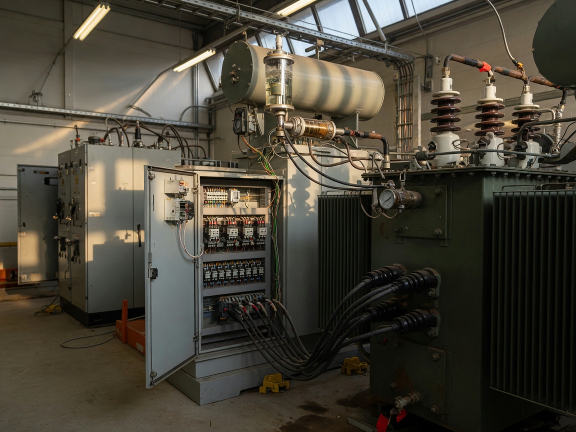
The differential protection system is the primary internal fault protection method for power transformers. It works by continuously comparing the current entering the transformer with the current leaving it. Under normal conditions, these two values are essentially equal. When an internal fault occurs — a winding short circuit, insulation breakdown, or inter-turn fault — the balance is disrupted and the relay trips instantaneously. Actual testing at a 380/132 kV substation in the Eastern Province demonstrated clearance times of under 25 milliseconds with a properly configured numerical differential relay. The main challenge in differential protection is distinguishing inrush current (which occurs during energisation) from genuine fault current. Both produce large differential signals. Modern numerical relays solve this by detecting the second harmonic content in inrush current and restraining the trip during energisation periods.
Overcurrent protection scheme
The overcurrent protection scheme serves as the primary protection for external faults and as backup for internal faults that differential protection might miss under certain conditions. It operates when the measured current exceeds a defined threshold for a set time period. Impedance relay settings must be coordinated carefully — too sensitive and you get nuisance tripping during load surges; too loose and fault clearance is dangerously delayed. In Saudi substations with large motor loads, the coordination study must account for motor starting currents, which can reach six to eight times the full-load current for a brief period.
Buchholz relay protection
The buchholz relay protection device is installed in the pipe connecting the main transformer tank to the conservator oil tank. It detects gas accumulation caused by internal arcing or insulation decomposition. The relay has two operating thresholds: a light-gas alarm (indicating slow internal deterioration) and a heavy-gas trip (indicating a fast, violent fault). Based on real cases in Saudi Arabia, the buchholz relay has proven invaluable for catching incipient faults weeks before catastrophic failure — but it is entirely ineffective on sealed, gas-filled (SF₆) transformers, which require different detection approaches.
Earth fault and overexcitation protection
Earth fault protection detects single-phase-to-ground faults, which are the most common fault type in HV transformer windings. Overexcitation protection monitors the volts-per-hertz (V/Hz) ratio and activates when the transformer's core approaches saturation due to over-voltage or under-frequency conditions. This is particularly relevant during grid frequency deviations — an increasingly important concern as renewable energy penetration on the Saudi grid grows in 2026.
Transformer protection relay types and selection criteria
Choosing the right transformer protection relay is not simply a matter of picking the most feature-rich device. It involves matching relay capability to the transformer's rating, the network's fault level, and the engineering team's ability to configure and maintain the equipment over its lifetime.
| Protection type | Operating principle | Typical operating time | Best application |
|---|---|---|---|
| Differential relay | Current balance comparison | < 30 ms | Primary protection, all ratings |
| Overcurrent relay (IDMT) | Time-current characteristic | 0.1–3 s | Backup and external faults |
| Buchholz relay | Gas/oil flow detection | Alarm or instant trip | Oil-immersed transformers only |
| Thermal overload relay | Thermal image model | Minutes (overload detection) | Transformer overload protection |
| Earth fault relay (REF) | Residual current detection | < 100 ms | Single-phase ground faults |
| Impedance (distance) relay | Impedance measurement | Zone 1: < 30 ms | HV transformer backup |
Numeric vs. electromechanical relays
Numerical relays now dominate new installations across the GCC. They offer self-monitoring, event recording, and IEC 61850 GOOSE messaging that electromechanical relays cannot match. That said, many substations in Saudi Arabia's existing network still operate with conventional electromagnetic relays installed in the 1990s. Upgrading these systems requires careful attention to CT saturation levels and auxiliary power supply compatibility — the relay hardware changes, but the current transformers and wiring infrastructure may not.
Protective relay coordination principles
Protective relay coordination is the process of ensuring that the relay closest to the fault trips first, while upstream relays hold back as backup. A coordination time interval (CTI) of at least 0.3 seconds is the industry standard between successive protection tiers. Errors in coordination — commonly caused by incorrect impedance relay settings or outdated fault level data — are among the leading causes of unwanted transformer trips and extended outage durations in the region.
Fault detection and real-world case analysis
Transformer fault detection is most effective when multiple monitoring inputs are cross-correlated. A single relay activation is informative; the combination of differential relay operation, elevated buchholz gas volume, and rising oil temperature tells the full fault story.
Step-by-step fault response procedure
- Acknowledge relay alarm and record the exact time, relay type, and phase indication from the SCADA dashboard.
- Isolate the faulted transformer by opening both HV and LV circuit breakers; confirm CB position via remote indication.
- Inspect the buchholz relay gas collection chamber — sample the gas and send for dissolved gas analysis (DGA) testing.
- Measure transformer oil temperature and compare against the pre-fault baseline from the transformer oil temperature monitoring log.
- Perform insulation resistance (IR) and polarisation index (PI) tests on all windings before re-energisation approval.
- Analyse relay event records and oscillography to reconstruct the fault's origin, magnitude, and duration.
- Submit a fault report per SEC O&M documentation requirements before restoring the unit to service.
Case study: winding insulation failure at a Riyadh industrial substation
According to a documented incident at a 33/11 kV industrial substation in the Riyadh Second Industrial City, the differential protection operated correctly within 22 milliseconds of a turn-to-turn winding fault. Post-fault DGA analysis revealed elevated hydrogen and acetylene levels — classic signatures of electrical arcing inside the tank. The buchholz relay had generated a light-gas alarm 11 days earlier, which was logged but not acted upon. This case reinforces a point that engineers in the region encounter frequently: transformer insulation monitoring data is only valuable when it triggers a timely inspection workflow. Data without action is noise.
"The most dangerous transformer is not the one that fails suddenly — it is the one that gives you warning signs you choose to ignore. Dissolved gas analysis, partial discharge monitoring, and thermal imaging are the early-warning system. Use them." — Industry consensus reflected in IEEE Std C37.91 commentary on transformer protection best practices.
IEC standards and GCC grid requirements
Compliance with international standards is not optional for electrical substation protection in Saudi Arabia. It is contractually enforced by SEC on all EPC projects and forms the basis for insurance and liability assessment in the event of a major fault.
Key standards for transformer protection
IEC 60076 governs the construction and testing of power transformers. IEEE Std C37.91 provides guidance specifically on transformer protection relay application. IEC 61850 defines the communication architecture for digital substations, enabling seamless integration between protection relays, bay controllers, and station-level SCADA. For HV transformer maintenance in GCC substations, IEC 60422 covers the condition monitoring of insulating oil, directly supporting buchholz relay interpretation and DGA protocols.
GCC-specific considerations
The GCCIA interconnection grid operates at 400 kV and 230 kV. Any transformer protection scheme connected to this network must coordinate with the broader power system protection philosophy agreed among member states. Saudi Arabia's SEC Technical Standards document TS-S-01 specifies minimum protection requirements for transformers rated 5 MVA and above, including mandatory differential protection, restricted earth fault protection, and buchholz relay installation on all oil-filled units. Deviating from these specifications requires formal engineering justification and SEC approval — a process that typically adds months to project timelines.
2026 trends: smart protection and predictive monitoring
The landscape of power transformer protection is shifting decisively in 2026. The traditional model — detect, trip, repair — is being replaced by a predictive paradigm driven by data analytics and machine learning. Why are so many engineers resistant to adopting these tools? Often because the capital cost of sensor retrofit and software integration appears high upfront, even when the lifecycle savings are clearly documented.
IEC 61850 digital substation integration
IEC 61850-based digital substations allow protection relays to communicate via GOOSE (Generic Object-Oriented Substation Event) messages at sub-millisecond latency — far faster than hard-wired tripping schemes. In 2026, SEC's ongoing substation modernisation programme across the Western and Central regions is driving widespread adoption of this architecture. Numerical differential relays with IEC 61850 capability can share event data across the substation instantly, enabling interlocking and protection coordination that was impossible with conventional wiring.
AI-driven predictive fault prevention
Machine learning models trained on DGA data, partial discharge trends, and load history are now commercially available and being piloted at several major Saudi industrial facilities. These systems flag transformers at elevated risk weeks before any conventional protection relay would activate. The shift from reactive protection to predictive asset management represents the most significant evolution in power system protection methodology in decades. Of course, there are limitations — model accuracy depends on data quality, and poorly calibrated sensors produce misleading predictions. The technology is powerful, but it requires skilled implementation.
Common mistakes in transformer protection design
Even experienced engineers make avoidable errors in power transformer protection design. The consequences range from nuisance tripping to catastrophic fault escalation.
Mistake 1: assuming buchholz replaces differential protection
The buchholz relay is a mechanical device that responds to gas accumulation. It is slow to respond to fast-developing faults and completely insensitive to early-stage inter-turn shorts. The differential protection system, by contrast, responds in under 30 milliseconds. These two systems are complementary — neither can replace the other. Industry consensus is clear: power transformers rated 5 MVA and above must be equipped with both, configured as independent protection channels.
Mistake 2: neglecting HV transformer maintenance intervals
A common cost-cutting measure that backfires is extending HV transformer maintenance intervals without condition-based justification. The transformer overload protection relay settings may be correctly configured, but if the cooling fins are blocked with desert sand and the winding insulation is at 70% residual life, the protection scheme is defending a structurally compromised asset. Transformer oil temperature monitoring and periodic insulation resistance testing are the minimum acceptable maintenance activities — and in Saudi Arabia's climate, annual intervals are not sufficient for critical units operating at high load factors.
Mistake 3: poor coordination between primary and backup relays
When impedance relay settings are copied from an old coordination study without updating for new fault levels — a surprisingly common occurrence after network expansions — the coordination margins can collapse. The result is either simultaneous operation of primary and backup relays (which complicates fault analysis) or, worse, delayed clearance that allows fault energy to destroy the transformer before the backup relay eventually operates. Every major network change should trigger a full protective relay coordination review.
Conclusion
Effective power transformer protection in 2026 demands more than installing the correct relay. It requires a system-level mindset — coordinated primary and backup protection, continuous condition monitoring, compliance with IEC standards, and a clear incident response procedure backed by trained engineering staff. For Saudi Arabia's rapidly expanding power infrastructure, the cost of getting this wrong is simply too high. The engineers and organisations that invest in robust, well-maintained protection schemes today will avoid the far greater cost of transformer failure, grid instability, and extended unplanned outages tomorrow.
Frequently asked questions
Q: What is the most important protection for a power transformer?
A: The differential protection system is considered the most critical primary protection for power transformers. It detects internal faults within milliseconds by monitoring the current balance between the HV and LV windings, and it operates independently of external network conditions. It should always be paired with buchholz relay protection and overcurrent backup schemes for complete coverage.
Q: How does a buchholz relay work in transformer protection?
A: A buchholz relay is installed between the main tank and the conservator of an oil-immersed transformer. It detects gas produced by internal arcing or insulation decomposition. Slow gas accumulation triggers an alarm; rapid gas or oil surge caused by a violent internal fault triggers an immediate trip signal. It is suitable only for oil-filled transformers.
Q: What standards govern power transformer protection in Saudi Arabia?
A: The primary standards are IEC 60076 (transformer construction), IEEE Std C37.91 (transformer protection relay application), and IEC 61850 (digital substation communication). Saudi Electricity Company's technical specification TS-S-01 defines local minimum protection requirements for all transformers rated 5 MVA and above connected to the SEC grid.
Q: What causes most power transformer failures?
A: Winding insulation failure accounts for 40–50% of transformer faults, according to IEEE research data. Contributing factors include thermal overload, moisture ingress, partial discharge activity, and harmonics from non-linear loads. Regular transformer insulation monitoring and dissolved gas analysis are the most effective tools for identifying deterioration before it leads to failure.
Q: Can transformer protection be upgraded without replacing the transformer?
A: Yes. Modern numerical protection relays can be retrofitted to existing transformers by replacing only the secondary relay panel, provided the existing current transformers meet the accuracy class requirements of the new relay. IEC 61850-compatible relays can then be integrated with SCADA systems, significantly enhancing monitoring and event-recording capability without any modification to the transformer itself.
More news
We will send you real-time information regularly!

Optical storage charging solution supplier
Cangzhou Huarui Transformer Co., Ltd.
Address: Xinxing Town Industrial Zone, Qing County, Cangzhou, Hebei
All rights reserved©2024 Cangzhou Huarui Transformer Co., Ltd.
Powe : www.300.cn License city substation