

-
-

-
Blog

-
Contact


Product classification

GCK low voltage withdrawable switch cabinet
Low voltage switchgear series
- Details
-
- Commodity name: GCK low voltage withdrawable switch cabinet
GCK low-voltage withdrawable switchgear is mainly composed of a power distribution center, a motor control center and functional units. These units are installed in a closed metal cabinet in an up-down manner.
Overview
GCK low-voltage withdrawable switchgear is mainly composed of a power distribution center, a motor control center and functional units. These units are installed in a closed metal cabinet in an up-down manner. The horizontal busbar on the upper part of the cabinet connects the cabinets together; the functional unit side of the cabinet is connected in parallel to the vertical busbar. The cabinet is divided into four mutually isolated areas: horizontal busbar area, vertical busbar area, cable area and equipment installation area. The functional units are installed in small rooms in various places in the equipment area. When any functional unit has an accident, the power supply can be quickly cut off (in order to replace the spare functional unit), which will not affect the normal operation of other functional units and prevent the expansion of the accident.
This product is equipped with a complete and reliable grounding system and protective electrical, and all functional units can disconnect short-circuit current according to the specified performance. The incoming line unit has a four-stage protection feature, so it can ensure the reliability of power supply and the safety of equipment and system.Model meaning
G C K - 口 Closed switch cabinet Pull-out Purpose Code Main circuit scheme number Use environment
• The altitude of the place of use shall not exceed 1000m;
• The ambient air temperature shall not be higher than +50°C and not lower than -5°C. The average temperature within 24 hours shall not exceed +35°C. The temperature under storage and transportation conditions shall be between -25°C and +55°C, and shall not exceed 70C for a short time;
• The monthly average relative humidity shall not exceed 95%. At lower temperatures, a higher relative humidity is allowed. At +25°C, the relative humidity can reach 90%. The switch cabinet has been designed to take into account the occasional condensation phenomenon. If required, a temperature and humidity controller and a heating and dehumidification device can be installed in the switch cabinet to prevent the generation of condensation;
• The earthquake intensity shall not exceed 8 degrees. Horizontal acceleration ≤ 0.5g, vertical acceleration ≤ 0.3g;
• Vibration amplitude: When F < 10Hz, the amplitude is not more than 0.3mm; when 10Hz <F < 150Hz, the acceleration is not more than 0.1g;
• The switch cabinet installation inclination does not exceed 5°, and it is installed indoors.
• Pollution level: 3.Main features
• Compact design: a smaller space can accommodate more functional units.
• Strong structural versatility and flexible assembly. The C profile with a modulus of 25mm can meet the requirements of various structural forms, protection levels and use environments.
• Standard module design: It can be composed of standard units such as protection, operation, conversion, control, regulation, measurement, and indication, and users can choose to assemble them as needed. More than 200 assembly parts can be used to assemble cabinet structures of different schemes and form fixed partitions or drawer units.
• Safety: A large number of high-strength flame-retardant engineering plastic components are used to effectively enhance the protection and safety performance.
• High technical performance: The main parameters reach the contemporary international level.
• Compressed space: The three-dimensional degree is high, which can greatly compress the space for storing and transporting prefabricated parts.
• Easy assembly: No special and complex tools are required.Main technical parameters
project Unit Parameter Rated working efficiency Hz 50 Rated working voltage V 380、660 Rated insulation voltage V 660 Rated operating current Horizontal busbar A 630-4000 Vertical busbar 600 Rated short-time withstand current Horizontal busbar 80kA (effective value) 1 second Vertical busbar 80kA (effective value) 1 second Rated peak withstand current Horizontal busbar 176kA Vertical busbar 110kA Rated current of receiving current A 1000、1600、 2000、2500 Maximum current of feeding circuit A 400 Main circuit connector A 200、400 Auxiliary circuit connector A 10 Power frequency withstand voltage for 1 minute V 2500 Maximum capacity of control motor KW 155 Protection level IP40 Structural features
In the power center (PC) incoming line cabinet, the top is the horizontal busbar area, and the lower part of the horizontal busbar area is the circuit breaker room. The circuit breaker can be configured with domestic DW15C, ME and other series J. It can also be configured according to user needs. Various circuit breakers produced by foreign electrical companies, such as: F series circuit breakers produced by ABB, and intelligent circuit breakers. In general, the PC unit has a main circuit with a flip (including busbars), and when the rated current is 630A-1600A, it occupies a cabinet with an outer dimension of 800*1000*2200 (width x depth x height). The main circuit without flip occupies a cabinet with an outer dimension of 800*800 x2000 (width x depth x height). When the rated current is 1600A-3150A, it occupies a cabinet with an outer dimension of 100x10002200 (width x depth x height). The main circuit without flipping occupies a cabinet with an overall size of 1000*800*2200 (width x depth x height). The structure of the power center (PC) feeder cabinet is similar to the incoming line cabinet. When the feed current is 630A-1600A, a 1000 x 1000*2200 (width x depth x height) cabinet can be installed with two circuits, which are installed in an upper and lower arrangement.
Motor Control Center (MCC) switch cabinets are available in two types: wall-mounted and non-wall-mounted. The top of the cabinet is the horizontal busbar area. Below the horizontal busbar area is the drawer functional unit area. The width of this area is 600mm, and the height of the drawer functional unit area is 1840mm. When the cabinet is installed against the wall, the left part of the cabinet is the functional unit area, and the right part has a 200mm wide cable outlet area. The cabinet dimensions are 800*500*2200 (width x depth x height). When the cabinet is installed away from the wall, the cabinet width is 600mm, and the cable outlet area is at the back of the cabinet. The cabinet dimensions are 6008001000) *2200 (width x depth x height). The cabinet depth is 800 and 1000. We recommend that users choose a 1000-depth cabinet to match the PC cabinet depth. When the drawer is pulled out of the cabinet, the live parts in the cabinet are not exposed, which is safe and reliable.
The drawer functional unit and the door are mechanically interlocked by the operating mechanism of the main switch. The door cannot be opened when the main switch is in the closed position, and the operating mechanism can be locked in the closed or open position with an external padlock. The functional unit compartments are separated by metal plates. The drawers have good interchangeability and have working positions, test positions and separation positions. When the drawer is pushed to a certain position, the drawer automatically positions. At this time, the drawer can be pulled on the left side of the drawer to release the position and enter the next position. The drawer also has an anti-falling function when it is pulled out of the cabinet.
The cabinets of fixed solutions such as capacitor compensation and metering have the same appearance and the same horizontal busbar position as the drawer cabinets. This ensures that the drawer-type and fixed cabinets can be used side by side.
The busbar of the busbar system cabinet adopts a three-phase five-wire system. When the rated current of the horizontal busbar is 1250A or less, a single busbar is used. When the rated current of the horizontal busbar is above 1250A, a double busbar is used. The horizontal busbars between cabinets are overlapped with connecting blocks. The vertical busbars are enclosed with polycarbonate engineering plastic shells. The partitions are used inside to limit the arc diffusion. The neutral busbar is set at the front of the cabinet top, and the protective busbar (PE) is set at the bottom of the cabinet and connected to the partition door of the cabinet, thereby ensuring the grounding continuity.
Without reducing the protection level of the shell, natural ventilation windows are provided at the bottom and top of the switch cabinet.
The protection level of the cabinet shell is IP40.Cabinet installation diagram (mm)
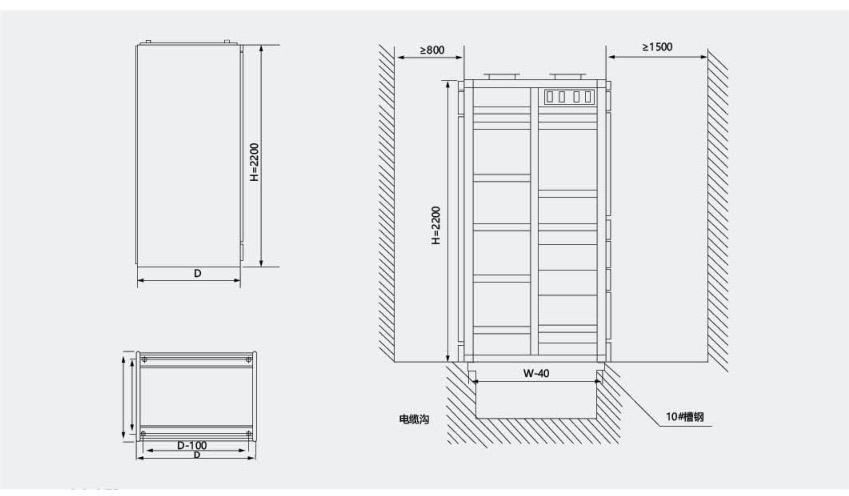
Cabinet width Cabinet depth Cabinet height 600×800×1000 6800×1000 2200 Busbar bridge installation diagram (mm)
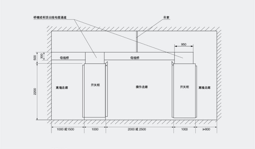
Product installation basic diagram

Product installation basic diagram
When installing this product, the horizontal lines between the cabinets should be connected firmly and reliably;
The door of this product has an interlocking function with the main switch, that is, the door can only be opened when the power is off. The other sides of this product are screw-sealed plates and have no interlocking function with the main switch. Therefore, please disconnect the power supply when removing the side panels of this product for maintenance;
Non-professionals should not open the cabinet for maintenance.
| About Huarui Power

The initial factory of Cangzhou Huarui Transformer Co., Ltd. was born in 1989. After developing and growing, it integrated resources and registered a company in July 2004. It is located in Cangzhou City, Hebei Province, which is known as "the first in the world in the hometown of martial arts.
Huarui Power, a high and low voltage power expert, and a supplier of optical storage and charging solutions, is a high-tech enterprise integrating R & D, design, manufacturing, product sales and service operations. It is a qualified supplier of State Grid, a qualified supplier of Sinochem Group, a qualified supplier of China's military enterprises, and the first brand of transformer in Cangzhou.
Huarui Power, its products cover energy-saving distribution transformers, box-type substations, high and low voltage complete sets of electrical equipment, power distribution automation, high-voltage cable branch boxes, etc., provide professional solutions for different industries and fields, and provide a variety of customized power consumption solutions according to the characteristics of customers' power consumption. The products are used in distribution networks and new energy projects, rail transit, metallurgy, petrochemical, real estate and other fields in all provinces and regions across the country.
| Enterprise Strength


Huarui Electric Power
Distribution transformer
Electrical equ
Previous Page
Next Page


| Product Messages
Get in touch with our team in a timely manner and be happy You offer help
* Note: Please be sure to fill in the information accurately and keep the communication unblocked. We will get in touch with you as soon as possible.
Subscription Information
We will send you real-time information regularly!
Optical storage charging solution supplier
Cangzhou Huarui Transformer Co., Ltd.
Address: Xinxing Town Industrial Zone, Qing County, Cangzhou, Hebei
All rights reserved©2024 Cangzhou Huarui Transformer Co., Ltd.
Powe : www.300.cn License city substation