

-
-

-
Blog

-
Contact





Products
PRODUCTS CENTER

Malaysia ZGS-Z Prefabricated Box Substation (American Style)
Category:
Product Description
Overview
ZGS series prefabricated box-type substation (commonly known as American box-type substation) has a "pin"-shaped structure. The transformer and high and low voltage equipment are closely connected. Among them, the transformer is exposed to the air on three sides, with good heat dissipation conditions, and can be separated from the high and low voltage equipment housings for easy maintenance.
The transformer adopts a sheet-type oil tank, no oil pillow, and a fully enclosed 813 series oil-immersed transformer. The high and low voltage bushings, tap switches, oil level indicators, pressure relief valves, oil drain valves, etc. are all installed on the end plate of the high-voltage cabin body. The position is reasonable and easy to observe and operate. The high-voltage cabin and the low-voltage cabin are separated by steel plates. The transformers of the high-voltage cabin and the low-voltage cabin are relatively independent, and they maintain a complete box-type transformer as a whole, with a compact structure, small size, and light weight. The distribution switchgear is installed on the high and low voltage sides.
Model meaning
| YBD | 口 | - | 口/口 | - | 口 | / | 口 |
| Prefabricated substation | Performance level code | High voltage wiring scheme |
|
Transformer rated capacity | Voltage level |
Conditions of use
• Cooling conditions: air self-cooling;
• Altitude: ≤1000m;
• Ambient temperature: outdoor ambient temperature is not higher than 40°C, not lower than -45*C; monthly average temperature does not exceed 30°C, annual average temperature does not exceed 20°C;
• Relative humidity: at 25°C, air relative humidity does not exceed 95%, monthly average does not exceed 90%;
• Shockproof level: horizontal acceleration is not greater than 0.3m/s, vertical acceleration is not greater than 0.15m/s";
• Surrounding environment: the installation environment should be free of obvious dirt, explosive, corrosive gases and dust;
• Installation site: there should be no severe vibration and shock, and it is required to be installed on a cement platform or other flat and solid platform;
When the above normal use conditions cannot meet the use requirements, the user shall negotiate with the manufacturer.
Main technical parameters
| project | Unit | Parameter |
| Rated voltage | kV | 10/0.4(high pressure/low pressure) |
| Maximum operating voltage | kV | 12 (high voltage side) |
| Rated frequency | Hz | 50 |
| Rated capacity | kVA | 50-1600 |
| 1 minute power frequency withstand voltage | kV | 35 |
| Lightning impulse voltage | kV | 75 |
| Cooling method | Oil-immersed self-cooling | |
| High-voltage backup fuse breaking current | kA | 50 |
| Plug-in fuse breaking current | kA | 2.5 |
| Ambient temperature | ℃ | -35~+40 |
| Allowable coil temperature rise | ℃ | 65 |
| No-load voltage regulation | ±5%or±2×2.5% | |
| Noise level | db | 50 |
| Protection level | IP43 |
Basic structure
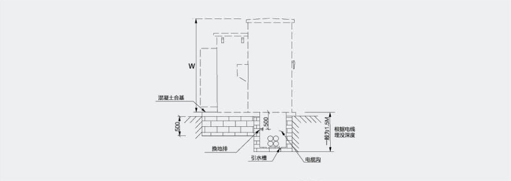
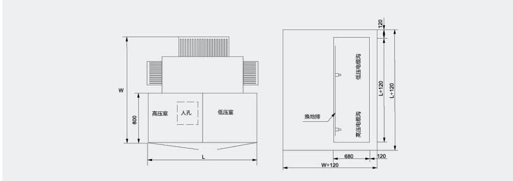
The box-type substation should be installed on a horizontal concrete table, and the table should be guaranteed to bear its weight. Because most of the weight of the box-type transformer is concentrated in the rear of the box where the transformer body is installed, and most of the front cabinet is empty and light, the rear of the platform must be strong to bear the weight of the combined transformer. At the same time, the front and rear tables must be flat (generally, if it is difficult to make it flat, the foundation of the front cabinet can be made slightly lower than the foundation of the rear transformer body, and it can be sealed with concrete after it is in place) to ensure that the box-type transformer is installed smoothly.
Technical requirements
• The surface of the concrete base should be flat. After the combined substation is installed, the base should be sealed with cement. .
• The shape of the grounding bar and cable fixing bracket can be determined according to the actual situation;
• The cable fixing bracket and grounding bar should be pre-buried;
• The position of the inlet and outlet cable holes depends on the specific situation;
• After the combined transformer is installed, there must be a gap of no less than 1.5m on the front of the switch to facilitate operation;
• The grounding grid can be made of 12 galvanized round steel or 30x4 galvanized flat steel, and the grounding wire resistance should meet the requirements of the power department.
Note: L, W. H dimensions are determined according to the actual project configuration.
We will send you real-time information regularly!
Optical storage charging solution supplier
Cangzhou Huarui Transformer Co., Ltd.
Address: Xinxing Town Industrial Zone, Qing County, Cangzhou, Hebei
All rights reserved©2024 Cangzhou Huarui Transformer Co., Ltd.
Powe : www.300.cn License city substation